Introduction to Plant 3D Isometrics
In the realm of CAD design, Plant 3D isometrics play a pivotal role in presenting complex piping layouts and systems in a clear and concise manner. These drawings are essential for engineers and designers to effectively communicate plans and specifications to diverse stakeholders. Understanding the fundamentals of isometric drawings not only enhances clarity but also bolsters project efficiency. In this article, we will delve into the intricacies of Plant 3D isometrics, helping you master this essential tool for plant design.
What are Plant 3D Isometrics?
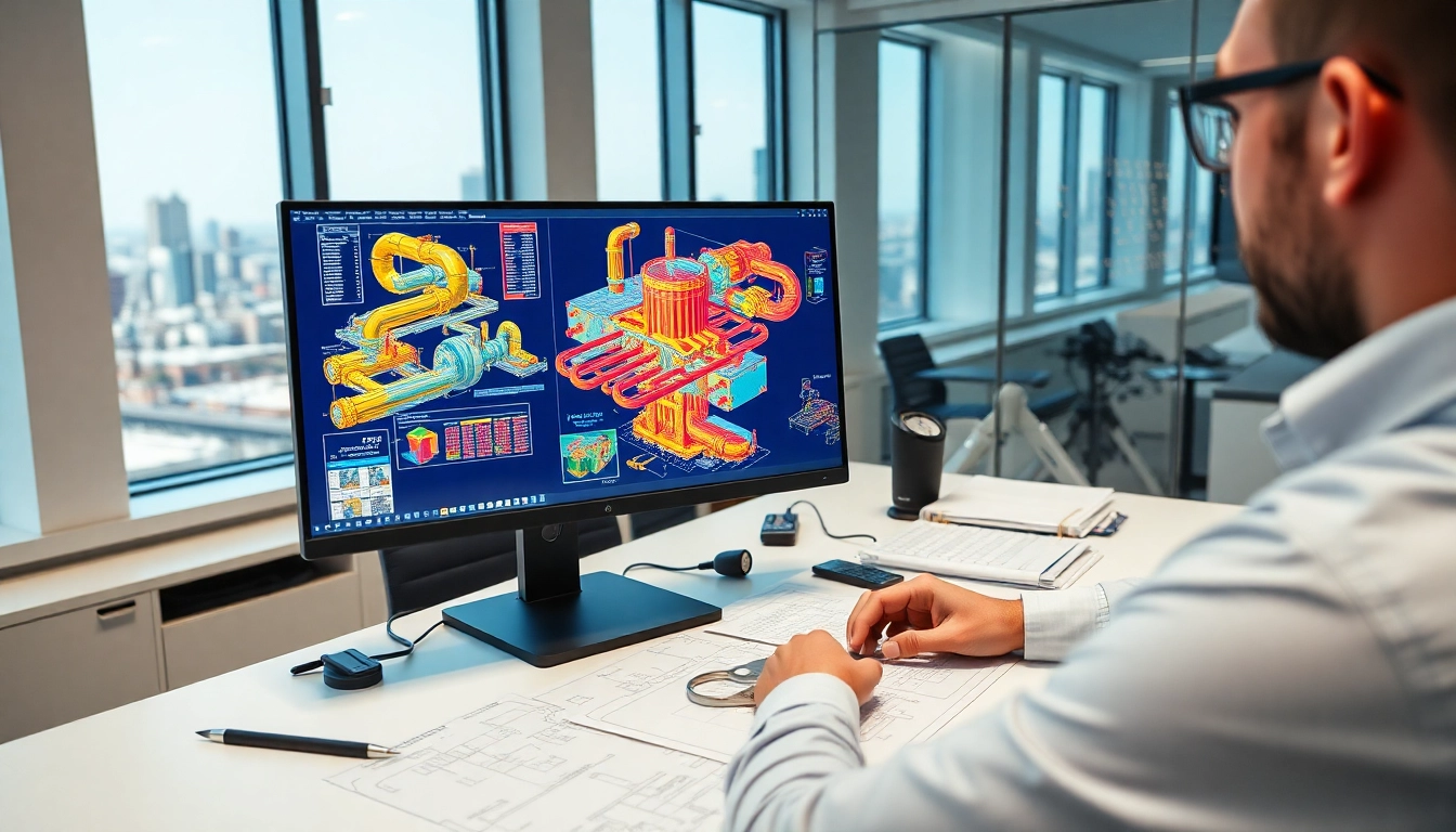
Plant 3D isometrics are simplified, scaled representations of three-dimensional piping systems. This method uses parallel projection to illustrate the piping layout without the complexities that can arise in full 3D views. Isometric drawings maintain the proportions and angles of the pipes as they would appear in a physical layout, allowing for easier interpretation by both engineers and non-technical personnel.
The Importance of Isometrics in Plant Design
Isometric drawings serve several crucial functions in plant design. First, they ensure consistency throughout the documentation process, providing a standardized format that is recognizable across different projects. Secondly, they simplify the communication of plumbing and piping systems, helping all team members—from designers to construction staff—understand the layout and specifications at a glance. Thirdly, these drawings facilitate efficient project planning, as they help identify potential issues before physical implementation is attempted.
Key Features of Plant 3D Isometrics
Several key features characterize Plant 3D isometrics:
- Dimensioning and Scaling: Accurate dimensions assist in the layout and measurement of components.
- Standard Symbols: Use of internationally recognized symbols for valves, pumps, and other components aids comprehension.
- Customization Options: Ability to adjust line weights, symbols, and labeling to meet specific project needs.
- Automatic Updates: Changes made in the 3D model propagate to the isometric drawings, ensuring documentation is always current.
Core Concepts of Plant 3D Isometrics
Understanding Basic Configurations
When starting with Plant 3D isometrics, understanding the basic configurations is essential. This includes familiarity with the menu settings and generator options within the software. Users can customize the isometric templates, which governs how the final drawings will look.
Key configurations typically involve setting the appropriate scale, defining symbol libraries, and specifying output formats. By establishing a clear configuration at the outset, users minimize errors and enhance clarity in their documentation.
Common Challenges in Isometric Creation
While creating isometric drawings can streamline design processes, several challenges can arise:
- Extraction Errors: Mistakes during the extraction process can result in inaccuracies in the final drawings.
- Cluttered Drawings: Overly complex isometrics can lead to confusion if not designed with clarity in mind.
- Software Compatibility: Ensuring that all elements work seamlessly across different CAD platforms can be troublesome.
To tackle these challenges, familiarize yourself thoroughly with the extraction process, utilize layers to control visibility, and validate the output frequently.
Best Practices for Efficient Workflow
To optimize your workflow while working with Plant 3D isometrics, consider the following best practices:
- Template Utilization: Create and use standard templates to expedite the drawing process.
- Frequent Updates: Regularly update components in your 3D model to reflect in your isometric drawings.
- Leverage Automation: Use automation tools available within the software to handle repetitive tasks.
Advanced Techniques for Plant 3D Isometrics
Customization of Isometric Drawings
Advanced customization of isometric drawings allows for personalized adjustments that enhance readability and aesthetics. Users can alter line styles, colors, and annotations specific to project requirements. For instance, highlighting critical paths or differentiating between various types of components can significantly improve the effectiveness of the drawings.
Integration with Other CAD Tools
Integrating Plant 3D isometrics with other CAD tools can amplify productivity. By transferring components between platforms or using supplementary software for specialized analyses, designers can explore innovative solutions. This integration can streamline the design process, ensuring that all aspects of a project remain aligned.
Performance Metrics for Isometric Drawings
Evaluating the performance of isometric drawings is critical for maintaining quality and efficiency. Some performance metrics to consider include:
- Accuracy: Measure how closely the isometric aligns with the physical design.
- Time Efficiency: Assess the time taken from model creation to isometric extraction.
- Stakeholder Clarity: Gather feedback on how easily team members can interpret the drawings.
Establishing these metrics enables continuous improvement and contributes to the success of future projects.
Real-World Applications of Plant 3D Isometrics
Case Studies of Successful Implementations
Numerous case studies illustrate the effectiveness of Plant 3D isometrics. In several industrial setups, teams that adopted isometric drawing practices reported reduced errors and faster project turnover. For example, a team responsible for retrofitting chemical plants found that using isometrics allowed for clearer communication with construction crews, resulting in decreased change orders and rework.
Insights from Industry Experts
Industry experts consistently emphasize the value of isometric drawings in plant design. Many advocate for their mandatory inclusion in project deliverables, citing improved understanding among contractors and team members. As plant design continues to evolve, experts predict that the demand for isometric capability will only increase, making proficiency in this area critical for future architects and engineers.
Future Trends in Isometric Design
As technology advances, the future of isometric design appears to be leaning toward greater automation and integration with emerging technologies. Innovations such as AI-driven predictive modeling could refine how isometric drawings are generated. Enhanced collaboration tools that allow for real-time updates and sharing across teams will further streamline the overall design process, solidifying the role of Plant 3D isometrics in future projects.
FAQs about Plant 3D Isometrics
What software do I need for Plant 3D Isometrics?
You typically need AutoCAD Plant 3D, which facilitates isometric drawing generation.
How can I improve my workflow in Plant 3D Isometrics?
Focus on understanding key configurations and using templates for efficiency.
What are common mistakes in creating Isometrics?
Not aligning dimensions properly and neglecting updates in the isometric styles can lead to errors.
Can I customize isometric symbols in Plant 3D?
Yes, Plant 3D allows customization of symbols suited to your specifications.
How do I share my Isometric settings?
You can share settings by copying configuration files to other project folders with matching parameters.